Electromagnetic (EM) filters are used in many electronic systems, ranging from cellular base stations to radars for aerospace and defense. It is common knowledge that wireless systems always have some form of an antenna that sends/receives EM signals. But what is perhaps less known is that, behind any antenna, there is an electronic network where signal filtering has a valuable function.
The complete design and analysis cycle of EM filters can be conducted within CST Studio Suite® [1]. One particular solution is a special optimizer that is based on the extraction, by Filter Designer 3D (FD3D), of a so-called ‘coupling matrix’. This matrix serves as a surrogate for the 3D geometry which enables the efficient automated tuning of a filter response. This is very useful as the user does not need to be an expert in all the details of the synthesis and implementation of complex filters.
An interesting novel filter design was shown by San Blas et al. [2] at the recent European Microwave Conference in Madrid in Sept. 2018. Some SIMULIA engineers returning from the event, intrigued by this configuration, quickly recreated the filter model in CST Studio Suite. Since it has a sensitive geometry, it had to undergo some optimization to get to a tuned filter response. This was no problem with the FD3D optimizer and therefore a good power match was quickly achieved over the channel bandwidth, as indicated by the low reflected signal shown in Fig. 1.

This optimization capability also allowed the engineers to go one step further and adjust the goals for a new set of filtering specifications. In these devices the attenuation outside the channel is another important figure of merit and to that end zeros are moved into the transmission response. A specific attenuation level of 50 dB for the upper stop band was specified as a goal for this model, as shown in Fig. 2. This level was successfully achieved after another run of the FD3D-based optimizer.

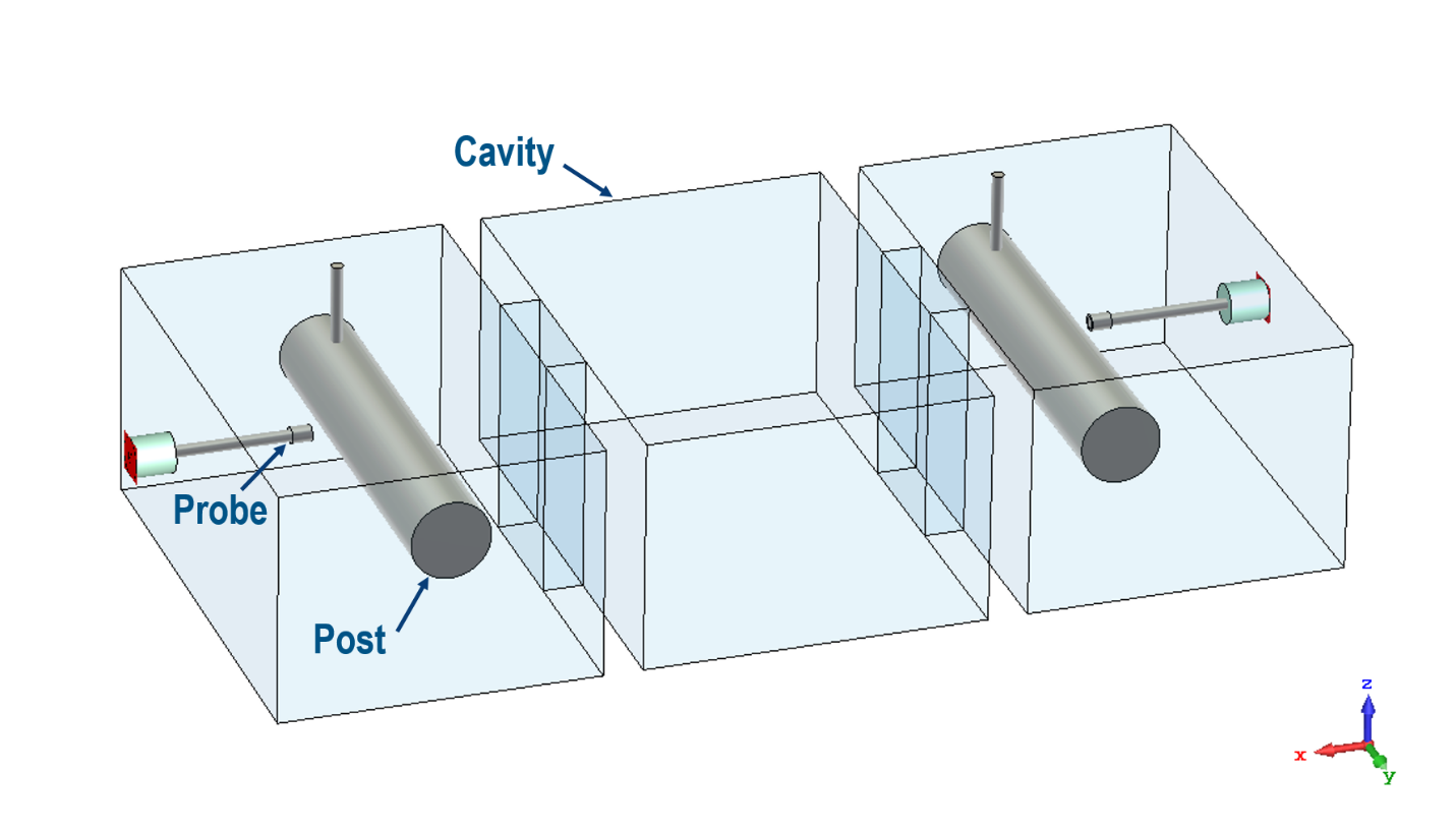
The original model had a transmission zero at about 12 GHz and, as seen in Fig. 2, it was brought down to 10.5 GHz to achieve the attenuation mask. This was achieved by increasing the magnetic field coupling between the input and output coaxial posts in the 3D model, shown in Fig. 3. It required bringing the posts physically closer to each other while detaching the feeding probes from them. The final push came by slightly increasing the height of the cavities. These changes were empirically brought about while the optimizer then took care of achieving the exact dimensioning.

References
[1] “Overview of CST Studio Suite Filter Design Technology”, SIMULIA eSeminar. [Online]. Available: https://www.cst.com/solutions/article/filter-design-technology-2017[2] A. A. San Blas, J. C. Melgarejo, V. E. Boria, and M. Guglielmi, “Novel Solution for the Coaxial Excitation of Inductive Rectangular Waveguide Filters,” in The 48th European Microwave Conference, Madrid, Spain, September 2018.
Want to find out more? Check out our eSeminars on Filter Design: