
By leveraging wind propulsion-assisted technologies, the maritime industry can address environmental challenges, improve operational efficiency, and contribute to a more sustainable future for global shipping.
By Katie Corey
Intro
In response to the growing need for reduced energy consumption and the imperative to minimize carbon emissions, there has been a surge in the development of numerous energy-saving and cutting-edge technological ideas.
The urgency to find alternative propulsion methods requires innovative approaches and Wind-Assisted Propulsion is postulated to lead the change. Rooted in ancient maritime practices, it emerges as a key enabler in the decarbonization journey, with various types such as rotor sails, kites, suction wings, and rigid sails.
Regarding the goals outlined in the Paris Agreement, the International Maritime Organization (IMO) aims to achieve a minimum 40% reduction in total annual greenhouse gas (GHG) emissions by 2030, compared to the levels recorded in 2008.
The IMO accepted recently CFD as a reliable method for calculation. January this year, Bureau Veritas, one of the main Classification Society for the marine industry, published the Wind Propulsion Systems – NR206 R02 rule:
“The wind force resulting from the operating conditions of the wind propulsion system defined in [4.2.1] are to be deduced from a Computational Fluid Dynamics calculation (CFD), wind tunnel tests or by an equivalent calculation method to the satisfaction of the Society.”
Dassault Systèmes has become a pivotal force in implementing digital technologies in shipbuilding and marine environments. Our focus lies in integrating Wind Assisted Propulsion Systems, as the most sustainable solution to reduce fuel consumption through retrofitting sails on existing ships.
Benefits of Wind Assisted Ships Propulsion (WASP)
By leveraging wind propulsion-assisted technologies, the maritime industry can address environmental challenges, improve operational efficiency, and contribute to a more sustainable future for global shipping.
This innovative approach serves as a free and sustainable energy source, eliminating the need for energy storage batteries. Moreover, the technology enables ships to cover longer distances with reduced fuel usage, further contributing to cost savings.
Methodology and Workflow
The workflow highlights a sequential fluid-structure interaction (FSI) optimization simulation of the isolated sail geometry through a parametric CAD design. The democratization of this process is extended on the 3DEXPERIENCE platform, enabling the shift towards high-fidelity simulation methodology to an earlier stage.
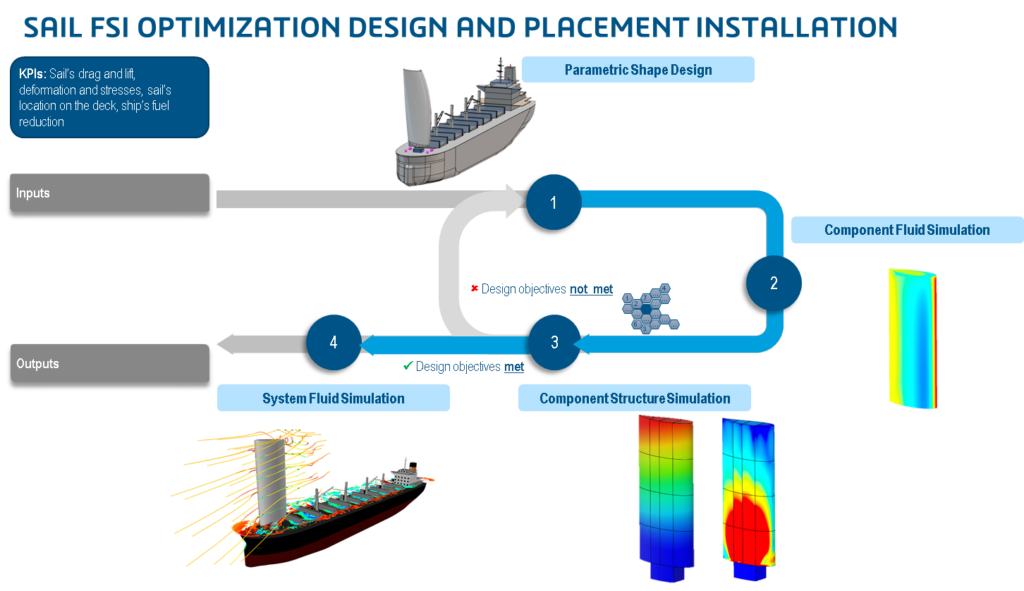
The initial phase involves the generation of parametric CAD geometry, wherein the outer and inner configurations are precisely defined. This includes specifying details such as the quantity and dimensions of wing ribs and wing spars. The entire hull, including elements like superstructures and cranes, is also established during this stage. Additionally, all material properties involved in the design are explicitly outlined in this phase.
In this process, once the parametric CAD is created, the designer computes a sequential FSI starting with the steady aerodynamic performance of the isolated sail, through a CFD fluid simulation on the 3DEXPERIENCE platform. This is a single-phase and steady-state N-S simulation, where it is set as the flow velocity and extracted as the main KPI, with the pressure distribution along the sail. This region mapping will be AUTOMATICALLY used as an input for the sequential FSI Structure simulation.
Subsequently, the structural simulation of the isolated sail is performed. All internal connections are defined in this step. This static and implicit structural simulation is also done on the 3DEXPERIENCE platform, getting the main KPIs: the stresses and deformations.
If the design objective is not met, the designer can define alternatives using optimization and approximation models, iterate on the external shape or size of the geometry to improve aerodynamics, or change covering materials or thickness to improve structural integrity.
If the design objectives are met, the first loop finishes.
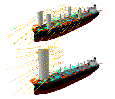
To handle the limited deck space available on a cargo ship, the second loop of this workflow is used to optimize the placement of the sail and its installation. This system simulation provides a high-accuracy unsteady VLES CFD based on LBM, where the cross flow and the impact of the sails over the cargo ship are analyzed depending on the compass rose the engineer set up. This allows us to define the proper placement on the deck and compare different configurations like this 1 vs 4 sails:
This sequential cosimulation can be optimized using the automated Process Composer on the 3DEXPERIENCE platform, where the designer defines the KPIs to maximize and minimize and the algorithm automatically performs the iterations over the geometry.
Customer Testimonial
“Thanks to SIMULIA and the 3DEXPERIENCE platform, we have superb renderings showing the flow lines called streamline, illustrating the deformed air around the trimaran,” describes Antoine Gautier. “We have quality images that allow us to identify the points that create a trail. These visual simulations are very useful and reliable. Thus, we discovered streaks that had not been identified, particularly around the rear arm, which led us to modify the geometry of the fairing.”
“Thanks to SIMULIA and the experts at Dassault Systèmes, we were able to significantly improve the aerodynamics of the boat, which, I hope, will result in exceptional performance gains on the water,” declares Antoine Gautier. “After having integrated all the elements tested on the trimaran, we should achieve a 70% improvement in aerodynamic drag. This is the only area in which we can make such progress.”


